
Differences Between 3,4, and 5 Axis Machining
Understanding Axis Machining Types and Their Core Capabilities
3, 4, and 5 Axis Machining – When to Use Each
1. 3 Axis Machining: The Foundation of Simple, Cost-Effective Fabrication
A 3 Axis Machining system operates by moving the cutting tool along three linear axes—X (left/right), Y (forward/backward), and Z (up/down)—within a 3D space. This linear-only movement makes it ideal for shaping simple, flat or shallow 3D parts, such as brackets, plates, or basic molds.
Its key advantage lies in cost efficiency: the machinery has lower complexity, requires minimal setup time, and reduces operational overhead—all of which boost profit margins for high-volume production of straightforward components. For example, manufacturing aluminum mounting plates for electronics relies heavily on 3 Axis Machining, as the part only needs three core processes: face milling (smoothing the top surface), edge profiling (shaping the plate’s perimeter), and drilling (adding holes for fasteners)—all of which are easily completed with linear axis movements.
2. 4 Axis Machining: Rotation for Cylindrical and Curved Features
4 Axis Machining builds on the 3 Axis setup by adding one rotational axis (typically the A-axis, which rotates around the X-axis). This extra axis allows the workpiece to spin while the tool moves linearly, eliminating the need for manual repositioning and unlocking capabilities for parts with wrapped or curved features.
It excels at components where features follow a cylindrical shape—such as slots on a valve stem, angled holes along a curved surface, or grooves on a pulley. A 2023 manufacturing report highlighted a critical benefit: shops using 4 Axis Machining for cylindrical parts saw a 28% reduction in setup time compared to 3 Axis systems (which require multiple repositionings). By avoiding manual flipping or resecuring of the workpiece, 4 Axis also improves accuracy and consistency, reducing human-induced errors.
3. 5 Axis Machining: Versatility for Complex, Multi-Sided Precision
5 Axis Machining is the gold standard for highly contoured, multi-sided parts. It adds two rotational axes (usually the A-axis, rotating around X, and C-axis, rotating around Z) to the three linear axes, enabling the cutting tool to approach the workpiece from nearly any angle.
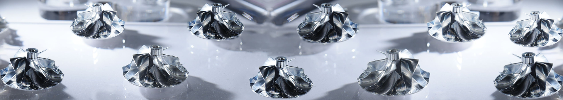
This versatility is indispensable in industries like aerospace and medical, where parts demand intricate geometries and ultra-tight tolerances. Examples include titanium turbine blades (with curved airfoils and internal cooling channels), hip implants (matching human anatomy), and aircraft structural components. Unlike 3 or 4 Axis systems, 5 Axis Machining completes complex parts in a single setup: for instance, a turbine blade can be fully machined without repositioning, achieving tolerances as tight as ±0.005mm and superior surface finish.
3 Axis vs. 4 Axis Machining: Efficiency and Application Boundaries
The table below compares core features of 3 and 4 Axis Machining to clarify their respective use cases:
|
Feature |
3 Axis Machining |
4 Axis Machining |
|
Axis Configuration |
X, Y, Z (linear only) |
X, Y, Z (linear) + 1 rotational (A/C) |
|
Best For |
Simple flat/3D parts (brackets, plates) |
Cylindrical parts with wrapped features (valve stems, pulleys) |
|
Setup Time |
Short (10–30 mins for standard parts) |
Moderate (20–45 mins, single setup) |
|
Material Versatility |
Works with most metals/plastics; limited by part shape |
Same materials; optimized for curved/cylindrical workpieces |
|
Tolerance Range |
±0.01–0.05mm |
±0.008–0.03mm |
Key Limitations & Advantages
- 3 Axis Machining struggles with parts that have undercuts, angled holes on curved surfaces, or wrapped features—these require multiple setups, increasing time and error risk.
- 4 Axis Machining solves this for cylindrical parts: for example, drilling 45° interval holes on a steel shaft is 3x faster with 4 Axis (the shaft spins to align each hole) versus 3 Axis (manual repositioning).
- However, 4 Axis fails with non-cylindrical, multi-sided parts (e.g., a cube with angled holes on three faces)—reorienting the part negates its efficiency.
4 vs. 5 Axis Machining: Precision vs. Complexity Tradeoffs
4 Axis Machining acts as a “middle ground” for complexity, but it cannot match 5 Axis’s ability to handle asymmetrical, multi-sided parts. Here’s how they compare:
1. Part Complexity Handling
5 Axis’s dual rotational axes let the tool “wrap around” the workpiece—critical for parts like carbon fiber aircraft wing ribs (with curved edges, internal lightening holes, and angled attachment points on all six sides). A leading aerospace manufacturer reported:
- 42% faster production time with 5 Axis vs. 4 Axis.
- Scrap rates dropped from 8% to 2% (single setup eliminates alignment errors).
2. Precision & Surface Finish
5 Axis systems use dynamic indexing to keep the tool perpendicular to the cutting surface, reducing tool wear and improving surface quality. For medical implants (e.g., knee replacements, where biocompatibility depends on smoothness):
- 5 Axis achieves Ra 0.4μm surface finishes.
- 4 Axis only reaches Ra 0.8μm.
3. Cost & Programming
5 Axis requires:
- Advanced CAM software (with simulation tools) to avoid collisions.
- Higher initial investment.
- This makes it less cost-effective for simple or low-volume parts—but invaluable for complex, high-precision components.
Matching Axis Machining to Material, Geometry, and Industry Needs
1. Axis Selection Based on Workpiece Material & Hardness
Material hardness directly impacts axis choice, as harder materials generate more heat and risk thermal distortion:
|
Material Type |
Recommended Axis Type |
Rationale |
|
Soft materials (aluminum 6061-T6, ABS plastic) |
3 Axis |
Easy to cut; linear movements achieve desired finish. |
|
Hard materials (stainless steel 316L, titanium Ti-6Al-4V) |
4/5 Axis |
Reduces setup frequency (4 Axis) or minimizes heat buildup (5 Axis). |
According to the 2022 ASM International Machining Guidelines:
- For materials with hardness >30 HRC (e.g., hardened steel), 5 Axis Machining extends tool life by 35% vs. 3 Axis.
- Example: Machining a hardened steel gear blank with 5 Axis uses a spiral tool path (distributes force/heat), extending carbide insert life by 50% vs. 3 Axis’s high-force straight cuts.
2. Industry-Specific Axis Requirements
Different sectors have unique demands that dictate axis selection:
|
Industry |
3 Axis Use Cases |
4 Axis Use Cases |
5 Axis Use Cases |
|
Automotive |
Engine brackets, sensor housings |
Drive shafts, fuel injectors |
High-performance racing cylinder heads |
|
Aerospace |
Simple structural brackets |
Basic cylindrical components |
Turbine blades, aircraft frames, satellites (91% of turbine blade makers use 5 Axis, per 2023 report) |
|
Medical |
Plastic tool housings |
Surgical instrument shafts |
Titanium hip implants, spinal rods |
|
Consumer Goods |
Plastic phone cases, aluminum cookware |
Bottle caps (threaded necks) |
Luxury watch casings (rare) |
Avoiding Common Axis Machining Mistakes
1. Mistakes in Axis Selection for Production Volume
- Overusing 5 Axis: For low-volume, simple parts (e.g., 50 aluminum brackets), 3 Axis costs 60% less (5 Axis hourly rates: $150–$300; 3 Axis: $50–$100).
- Underusing 5 Axis: For high-volume complex parts (e.g., 1,000 turbine blades), 4 Axis requires 3x more setup time than 5 Axis—raising labor costs and delays.
- Ignoring Geometry: Undercut parts (e.g., recessed slots on plastic housings) need 5 Axis; 3 Axis causes misalignment, 4 Axis can’t reach non-cylindrical undercuts. A 2023 study found 68% of 3/4 Axis scrap parts stem from this error.
2. Programming & Setup Best Practices
3 Axis
- Use basic G-code for linear movements.
- Employ quick-change fixture plates to reduce setup time (10–15 mins per part switch).
- Always run a dry test (no material) to avoid tool-fixture collisions (3 Axis tools are larger and more prone to impacts).
4 Axis
- Use CAM software with 4 Axis simulation to visualize rotation.
- Center the workpiece on the A/C axis (a 0.1mm offset causes dimensional errors).
- Secure cylindrical parts with chucks/collets for concentricity—one automotive supplier reduced errors by 40% with proper centering.
5 Axis
- Invest in advanced CAM software (e.g., Mastercam, SolidWorks CAM) with collision detection.
- Use a 5 Axis trunnion table to secure the workpiece (enables full rotation without repositioning).
- Train programmers on “lead angle control” (adjust tool angle to improve finish/tool life)—aerospace shops using this achieve 95% first-pass yields.
Step-by-Step Axis Machining Selection Process
Follow this framework to choose the right axis type for industrial applications:
1. Start with the Part: Geometry, Tolerance, Material
-
Geometry: Flat surfaces = 3 Axis; cylindrical/wrapped features = 4 Axis; multi-sided/contoured shapes = 5 Axis.
- Example: Flat aluminum plate (3 Axis); steel shaft with helical slots (4 Axis); titanium turbine blade (5 Axis).
- Tolerance: ±0.005mm or tighter = 5 Axis; ±0.05mm = 3/4 Axis.
- Material: Soft = 3 Axis; hard = 4/5 Axis.
A 2023 Precision Machining Report found shops that analyze parts first reduce axis selection errors by 55%.
2. Align with Production Volume & Cost Goals
|
Production Volume |
Simple Parts |
Complex Parts |
|
High (>1,000 units) |
3 Axis (low cost) |
4/5 Axis (faster setup) |
|
Low (1–100 units) |
3 Axis (economical) |
5 Axis (avoids excess setup time) |
Per the 2024 Industrial Machining Guide, “cost-volume analysis” (linking axis to quantity) cuts overall costs by 22%.
3. Evaluate Shop Resources
- Machine Availability: Use 3 Axis for simple parts if no 4/5 Axis machines; outsource complex work for low volumes.
- Programmer Expertise: Start with 4 Axis for moderate complexity if the team lacks 5 Axis experience.
- Fixture/Tooling: Ensure access to specialized tools (e.g., trunnion tables for 5 Axis) before selecting the axis type.